Accurate prediction of electromagnetic interference (EMI) is essential for the design of modern power electronic systems. As switching frequencies continue to increase, magnetic components such as transformers become significant contributors to both conducted and radiated emissions. The electromagnetic behavior of a transformer is influenced not only by its electrical characteristics but also by its physical structure, including the core geometry, winding arrangement, conductor placement, and spacing between windings. These geometric features determine the distribution of electric and magnetic fields and have a direct impact on the overall EMI performance of the system.
Limitations of Conventional Transformer Models
Engineers traditionally rely on electrical macro-models, such as S-parameter (.snp) files or SPICE/CIR models. While useful, these models introduce significant gaps in high-frequency analysis.
- Missing geometry: They capture terminal electrical behavior but do not represent the transformer's physical structure.
- Omitted physics: Crucial EMI drivers—such as near-field parasitic coupling, localized leakage flux, and structural radiation mechanisms—are not adequately represented.
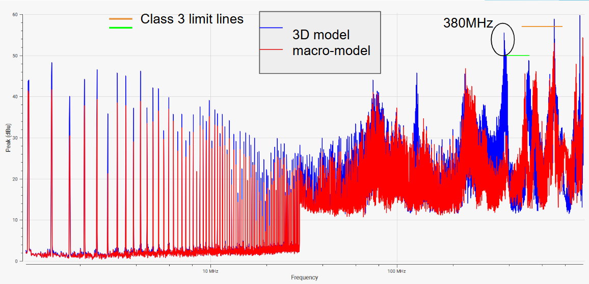
This limitation often leads to a mismatch between simulated EMI trends and actual laboratory measurements, particularly for radiated emissions in high-frequency power converter applications.
Need for a 3D Physical Model
A geometry-based transformer model enables electromagnetic simulations to account for the physical characteristics that influence EMI behavior. By representing the actual core and winding structure, the model provides greater insight into field coupling, leakage paths, and radiation mechanisms that are otherwise difficult to analyze using circuit-level models alone. This leads to a better understanding of transformer-induced emissions.
Feature Spotlight: 3D Transformer Generator
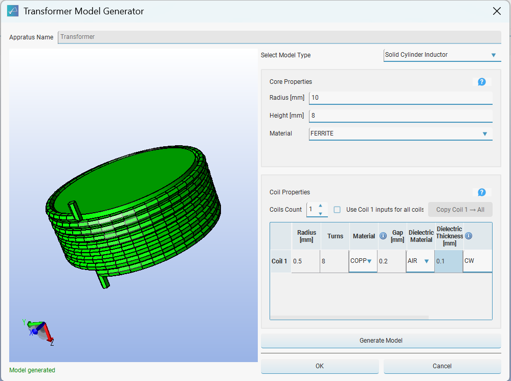
To address this need, Compliance-Scope 5.2.0 introduces a 3D Transformer Generator that creates a transformer model from user-defined physical inputs for direct use in EMI/EMC simulations. The feature also includes a lookup table that assists users in selecting appropriate physical dimensions and transformer parameters based on the desired inductance (L) and capacitance (C) values, simplifying the model creation process.
User-Configurable Parameters:
- Core Specifications: Core type (solid cylinder or solid rectangular),material and dimensions.
- Windings: Total number of windings, turns per winding, winding material, and cross-sectional dimensions.
- Spatial Placement: Precise air gaps and inter-winding spacing.

Benefits
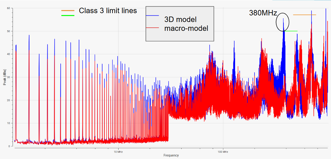
The generated 3D transformer model enables more realistic analysis of electromagnetic field distribution and geometry-dependent coupling effects, improving the accuracy of EMI prediction compared to conventional macro-models. It helps engineers evaluate the impact of transformer design on system-level emissions, identify potential EMI sources early in the design cycle, and achieve better agreement between simulation and laboratory measurements, thereby reducing design iterations and accelerating product development.
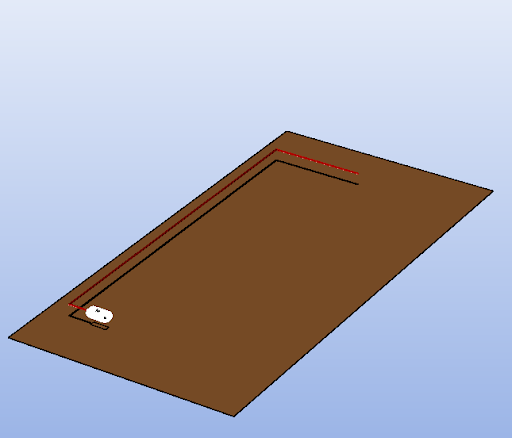
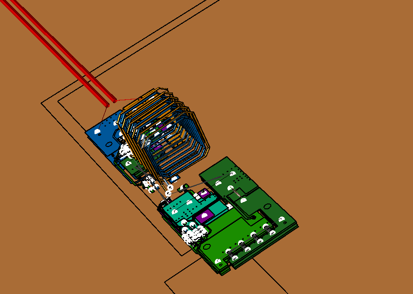
Fig. 3 shows a laboratory setup of CISPR 25 radiated emissions featuring the device under test (DUT) with the integrated 3D transformer model. The accompanying Ev(dBu) vs. frequency plot highlights how the conventional macro-model underestimates high-frequency emissions.
Ready to run your first simulation?
Get a technical walkthrough or schedule a demo with our engineering team